The Small Fall That Guided Water Over the Pont du Gard
The aqueduct bridge is an arresting mass of stone. The line of its old channel reveals another achievement: preserving a slight downhill route across a deep valley.
In this story 4 sections
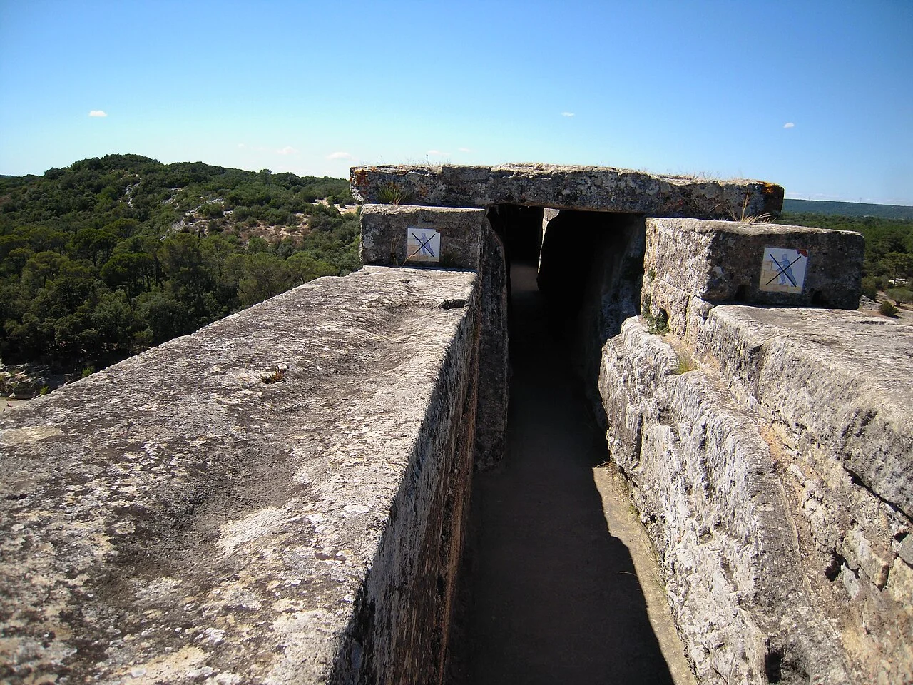
The Pont du Gard is much easier to see than the water it once carried. On the approach to the river, stone arches rise in three tiers, one above another. Most visitors can grasp the difficulty of setting so much material above the Gardon without knowing where the working part of the aqueduct went. Follow the arches upward to the narrow line at the top. It was the route for water coming from the direction of Uzès and travelling onward to Nîmes. The distance from the river below is striking. The height difference that mattered from one end of the channel to the next is harder to see.
The official site gives the aqueduct’s route as about 50 kilometres and reports an average fall of around 25 centimetres per kilometre. That rate turns a large horizontal distance into a surprisingly small change of level. If a straight kilometre were laid out at that mean grade, the end of the channel would be down by roughly the length of a hand. The whole route had local variations. The mean gives a sense of the narrow margin over the entire journey, and a reason to resist reading the exact fall through the bridge from the appearance of its top line in a photograph.
Height above the river and fall along the channel
Start with the two quantities that can be confused in a single picture. Height above the river is measured vertically from the lower landscape. Fall along the aqueduct compares the level of the channel at two places along its route. A bridge can place a channel high above a river while preserving a gentle decline in the direction the water needs to go. A high bridge does not require a steep water channel. It supplies the height at which the channel can cross a gap and pick up its course on the other side.
Put a pencil across two stacks of books and lower one end by a thin slip of paper. The stacks do most of the visible work in the model. The small difference in the height of their tops does most of the work in deciding which way a liquid would tend to move along a suitable open channel there. The actual crossing has multiple supports, a channel of finite size and stonework with its own weight. The model preserves one point: it is possible for a large structure to protect a very slight relationship between two levels. Keeping those quantities separate makes the monument’s upper edge more interesting than it first looks.
Now look at the bridge from the bank instead of treating a perfectly broad photograph as a survey. Parts that run away from a camera can appear to rise or fall because of perspective. One end of a wall may be more clearly outlined than the other. A line along the outside stonework is also different from the floor of a channel on the inside. For a measured slope, use a survey or engineering study that identifies what was measured and where. The photograph is better used to establish the presence of the channel above the arches and the relation of the bridge to the valley. Those are substantial things to see.
The water had to travel for much longer than the bridge
On a route map, the spring and the receiving city can feel close enough to join with one stroke. Terrain supplies the reason for much more work. The route has to keep declining and pass around or through ground that would obstruct the water. A route on the surface of a map may be short and cross a rise that cannot be negotiated at the required grade. A longer alignment can follow more favorable ground. In several places the usable line is visible only in surviving fragments. The bridge stands out because the valley made the channel conspicuous for a short time.
A bridge is one response to a difference between the line required for the water and the shape of the land underneath it. Tunnels, buried channels and stretches close to the surface address different relationships. Begin a sketch with a line for the ground and a point for the level of the source. Consider how quickly the ground can rise above a slightly descending route. The need to preserve a running course becomes obvious before a viewer has learned the name of any engineering instrument. A suitable route could be expensive to construct precisely because it had to keep a modest difference from place to place.
Look at the edges of the valley in the photograph. The stones do not need to occupy equally high stacks once the ground begins to rise. A channel crossing at a fixed general level can meet the slopes and continue. Much of the structure’s height is needed only where the ground falls away. There is an economy in making the long upper run depend on the supports required at each point below it. The picture gives a readily visible section of a set of decisions that would otherwise spend most of their length hidden in the terrain.
Water level depends on more than the grade
An average slope cannot tell you on its own how much water passed through a channel. Width, depth and the condition of the surfaces all affect the way water moves. A narrow path with a practical depth can carry useful flow, and a fill of sediment or mineral deposits would change the available shape over time. Ortloff’s hydraulic study considers the route as a system from its water intake to its receiving installation at Nîmes. That is a useful shift of scale. The bridge is one location where it is possible to understand some of the geometry of the whole system. A claim about delivery belongs to the course and its operating conditions as a whole.
A small open model can help separate these ideas. Imagine shallow water moving through a wide groove pitched a little down. Narrow the groove over part of the path or put a rougher texture on the bottom. The original difference in level is still present. The details of the actual movement can change. A user of a working aqueduct would have had a reason to care about keeping the passage open and making water available away from the part where the largest monument happens to survive. In a dry surviving structure, the spaces a builder gave the water are a different sort of evidence from the look of the surrounding masonry.
The question becomes more concrete at the receiving end. A channel that delivers water to a city needs somewhere for that water to arrive, especially if it is to be directed toward several parts of the city. The receiving installation at Nîmes studied by Ortloff is a way to put that last stage into the picture. The bridge shows how the line could be carried over a valley. The receiving works give a reason to ask how the water was taken from a single arriving course and offered routes onward. A visitor looking at these parts separately can see monumental walls at one place and openings at another. Following the water gives the openings an equal place in the account.
Notice the difference between the maximum space enclosed by a channel and the space normally occupied by its flow. A surviving top edge gives a limit to the old space. It does not identify a particular day’s water level. A mineral trace might provide a more direct clue about past contact with water, if the object record explains how it was interpreted. Use that evidence carefully when imagining the state in which the aqueduct usually operated.
Do not confuse the size of the aqueduct with the size of the river beneath it. The two routes meet in plan and at different heights. The Gardon does not become the ancient channel just because the arches are above it. The source and destination connect the raised channel to a different geography. A river photograph that includes the bank and a clean view of the upper level is particularly helpful here. You can begin tracing both directions and see that water is a visitor to this picture twice, once as the visible river and once as a former current near the top of the stonework.
Start the next visit at the top line
From an accessible viewing spot, make a first note about the high channel and the direction in which the larger route continued. Then pick out how many levels of stone stand beneath the part you were looking at. This order makes it easier to give the arches their proper job. They made a line across the valley available at the height needed for a channel. Looking first at the bulk of one pier makes it easy to admire the workmanship and stop short of the problem that made the pier necessary.
The bridge repays both views. Stand at river level and its height is immediately apparent. Look along the course of the former water, and most of its path disappears from the frame. It took a considerable bridge to keep one part of that longer line continuous. The glimpse at the top sometimes looks almost as straight as a ruled line. In use, it had to be the kind of line that could carry water onward without an abrupt stop. That tiny difference in level belongs beside the great difference in height when describing what was built.