How the Oseberg Ship Holds Its Planks
A hull can be recognized by the shape of its prow. A closer look at the Oseberg ship follows the narrow overlap that helps join one plank to the next.
In this story 4 sections
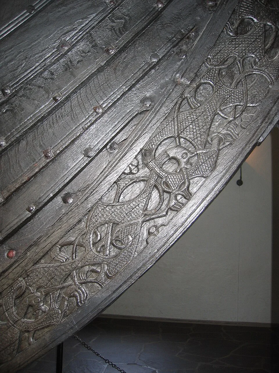
A photograph of the Oseberg ship can leave you with a strong impression of its prow and almost no memory of the length beside it. This is understandable. The ship’s carved timbers give a visitor something direct to follow. The body of the hull has a quieter group of lines. They continue away from the carving and partly disappear together around the curve. The interesting one to single out is the place where one long plank goes over part of another. It is a brief arrangement in cross-section, repeated over a great distance along the length of the boat.
The Museum of the Viking Age in Oslo describes Oseberg as a ship built in southwestern Norway in the ninth century, chiefly of oak, and later placed in a burial. The boat contained a variety of evidence by the time it entered a museum, much of it not reducible to a single period of use or one view. You can look at the surviving hull as an archaeological object and as an example of construction. To avoid confusing the two, begin with what the picture shows: shape, edges and different surfaces in the same direction. A seam can show a principle of construction without accounting for every use the boat had.
What the edge of the board says
Imagine looking at two planks in cross-section. In one arrangement their edges meet near the same plane, leaving a seam. In another, one extends part of the way over the neighboring board, and the points where they meet form an overlap. From outside the arrangement you can have a visible step. A person who sees that step often knows quite a lot about how the hull is made before seeing any of the fastenings. In a construction tradition known as clinker building, overlapping longitudinal planks are a characteristic part of the shell rather than a later decoration stuck on its side.
The overlap occupies an area, not just a fine engraved line. Two surfaces have to fit over a length that may move along curves. Picture a toy model made with two pieces of stiff paper. At the straight part a slight overlap may seem easy to maintain. As both pieces begin to bend, they can approach one another differently at different points. If they no longer lie together, a look at the two edges might call one area close and another open, even though a drawing from directly in front shows a continuous line. Taking the overlap seriously means taking the relationship of its surfaces seriously over the whole length.
Roskilde’s Viking Ship Museum explains the significance of the overlap to the structure of a clinker hull. A line of joined boards contributes to the shell in more than one direction. It helps create the shaped surface that meets the water, and the long arrangement of wood and fastening is part of what makes it act as a structure. Some people picture the boat primarily as a group of internal frames with the outside merely covering them. The overlap makes a good point of entry to another way of understanding it, in which the shell itself has significant work to do.
Look along, and then across
A row of overlaps brings relatively little trouble to the eye while you are following it along a straight part of the boat. It is more informative where the ends turn. Toward the upper part of the bow the shape needed of the planks changes. A line of a similar distance from its neighbor in a photograph may have a very different relation along its curve when you draw the sections. Look across several boards at one position, then follow one board to another position and look across it again. Both views help a student see how a built volume emerges from what appeared to be a decoration made of stripes.
Another useful trace distinguishes a single plank from a strake, a run along the hull that can consist of more than one piece. A long line across the side of a boat does not establish that every plank along that line came from one enormous piece of wood. Scan the material for differences that might identify sections within the run, then look to the appropriate museum description before making a definite claim. One length of seam between neighboring courses and a joining operation within a course answer different building questions. You can mark each in a way that leaves the other visible in your sketch.
A tool for this is a slow selection of reference points. Mark the line away from the prow, one dark rectangular section within the wood and a junction at one of the carved areas. Do not assume that every dark mark is an intentional fastening. A photograph can lose detail where the grain is dark or in shadow. If the fasteners matter, look for collection records and suitable close views. The pattern of attachments can be evidence even if you temporarily set aside an exact count or material for individual points you cannot see.
The surface has been a long time out of the water
A clinker boat in current use offers different evidence from the Oseberg ship. The materials and surfaces of an excavated wooden object have histories of burial, recovery, mounting and preservation. Some parts that mattered to the original construction can be hard to distinguish or absent. The Oslo museum notes, for example, that caulking material survives on the Tune ship where it is missing from the Gokstad and Oseberg examples. That comparison is more useful than treating a seemingly clear seam in today’s photograph as proof of how the builders addressed every joint.
Take three separate photographs in thought. One shows the hull under conditions in which people would be using it. Another shows a close view during recovery. The third shows the ship in a supporting arrangement as a museum object. Ask which view lets you assign a purpose to a line across the side and which one allows you to see subtle changes in the wood. Underwater parts of the shape are hard to see in the first view, while the other two give dramatically different support. There is no expectation that all three reproduce the same contours in the same way.
The modern holder is especially worth noticing. A section of conservator’s support can help keep an old ship in a necessary position. It does not record an original fastening on the boat. Equally, remarks about how the hull stood in the building at the date of a photo are not general observations about how these boats performed. A full account separates the object’s material characteristics, the inferences people have drawn about its working form and the documented measures a museum took to care for it.
On a tracing of two adjacent courses, make the line of each one continue a little farther than it appears in the original view. Compare the result with a larger photograph. Instead of tracing a new first outline, correct the path of that one course while retaining the others. This is a way of seeing how quickly an incorrect guess about the shape of a surface can run along the hull. It also gives the line a more physical meaning. A builder would have needed the edge to meet actual wood as it went, whatever its ideal position might have been on a drawing.
What a model leaves out
A small model can teach you to look at how parallel lines change direction. It can show why a set of flat strips is not yet a hull and why one seam can remain important far away from the spot at which you first saw it. It cannot tell you how the worked oak at a particular part of Oseberg responded to its own curves, what support it needed, or what happened to its joints in service. A model builder can make a persuasive continuous outline while using methods the original materials could not take. If the comparison matters, try observing the same relationship, such as the position of a step between courses, instead of expecting the whole things to be identical.
A museum case can make it look as though the board runs simply from here to there. Follow it a second time and ask what had to be prepared before it could occupy that route: what would have supported it, where the shape of the neighboring board could help determine the fit, and how an edge at one end can be made to continue into another feature. The complexity is less abstract if you treat the wood as several real pieces that had to meet rather than a large profile already visible to the boatbuilder.
Return to the prow after paying some attention to the hull. The carving can still be the first thing you would mention to a friend. You will now have a quieter second thing to show them, one that goes away from the photograph rather than concentrating inside it. A succession of overlapping edges helped the wood become a shaped whole. The viewer can follow the evidence with an eye moving along a line much longer than the one that originally attracted it.